


0.03mm Fine Wire Slow Wire Processing Gears
Xincheng is a professional CNC machining factory and also a manufacturer and supplier of processed parts in China. In the precision transmission system, the tooth profile accuracy and pitch error of 0.03mm Fine Wire Slow Wire Processing Gears directly determine the stability of equipment operation and transmission efficiency. Xincheng adopts the 0.03MM fine wire slow wire processing technology, breaking through the precision bottleneck of traditional processing techniques.
Send Inquiry
Product Description
Core Processing Advantage: Precision is defined by fine wire technology
Compared with the conventional Slow Wire Processing, the 0.03MM Fine Wire technology achieves an all-round upgrade of gear processing with the characteristics of "thinner wire diameter and more uniform discharge". The core advantages of 0.03mm Fine Wire Slow Wire Processing Gears are reflected in three dimensions:
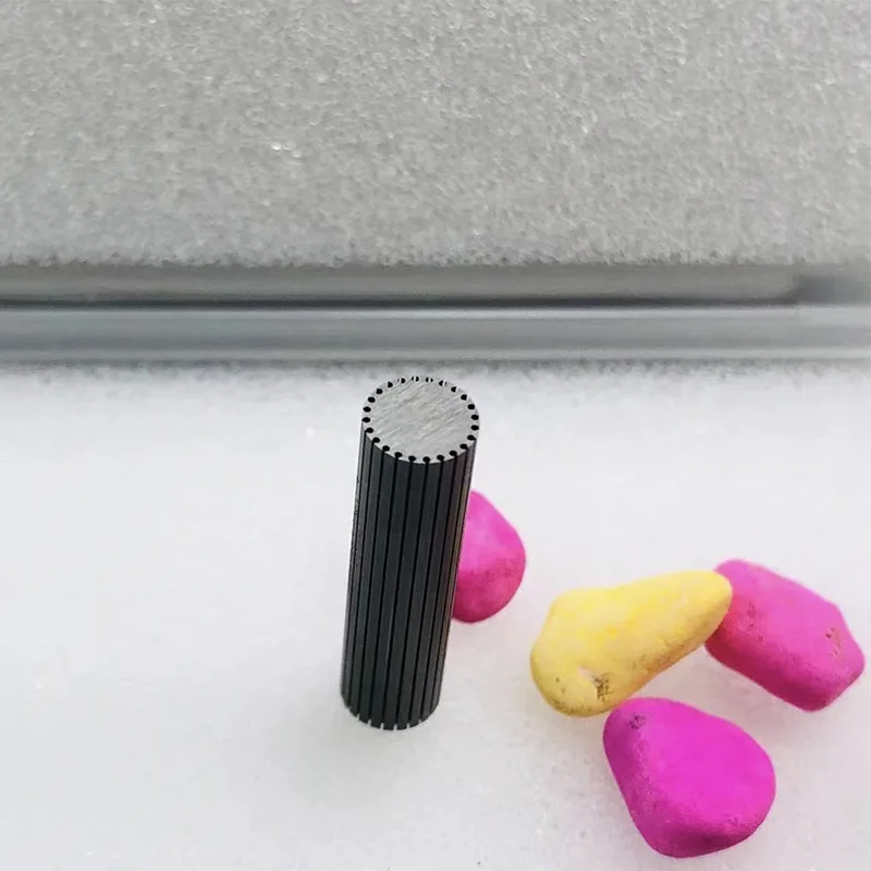
Ultra-fine tooth profile precision forming: 0.03MM fine lines can penetrate into the tooth grooves of micro gears with a module of 0.1 or less. The minimum processed tooth thickness can reach 0.05MM, and the tooth profile error is controlled within ±0.002MM. It perfectly regenerates complex tooth profile contours such as involute and arc, solving the problem of "tooth profile distortion" in the processing of micro gears.
Ultimate surface quality optimization: The surface roughness of the processed gears is as low as Ra0.1μm, which can meet the low-friction requirements of precision transmission without secondary polishing, reducing wear and noise during gear meshing and extending the service life of the transmission system by more than 30%.
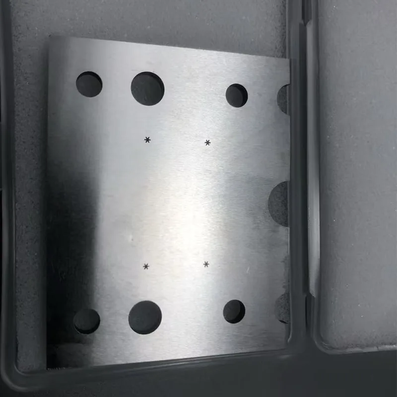
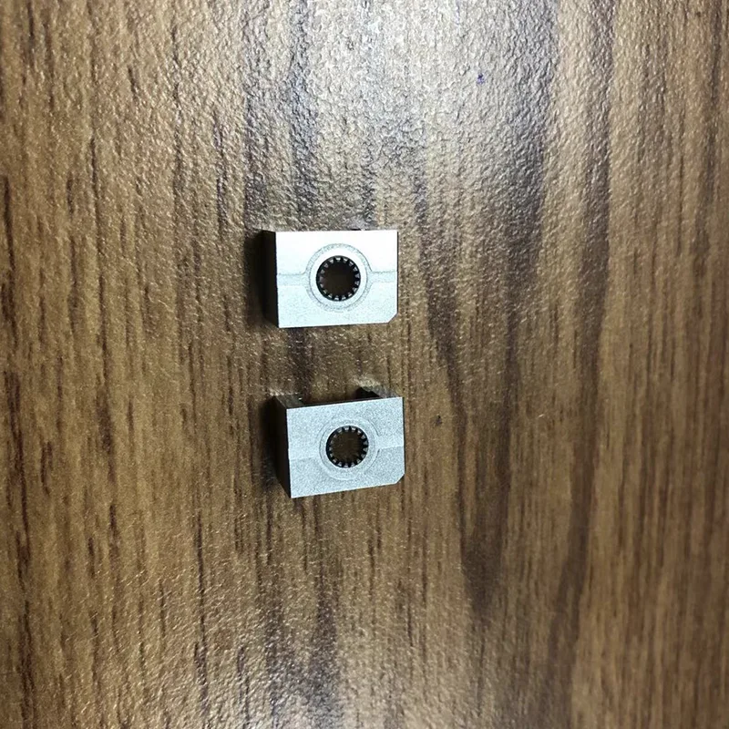
Complex structure integrated processing: Supports integrated processing of gears with composite structures such as keyways, steps, and inner holes, avoiding positioning errors caused by multi-process clamping. The consistency error of processing accuracy is ≤0.003MM, especially suitable for the requirements of integrated precision components.
Processing Flow
Relying on the full-process standardized control system to ensure that every 0.03mm Fine Wire Slow Wire Processing Gears processed product meets the customization requirements, our processing flow is as follows:
1. Drawing analysis and process planning: Engineers deeply analyze the 2D/3D drawings of gears, and based on the material characteristics, formulate fine wire feeding paths and discharge parameter plans, and issue processing technology sheets
2. Precision clamping and tool setting: Vacuum suction cups or precision fixtures are used for clamping, and a tool setting accuracy of ±0.001MM is achieved through a CCD vision tool setting system
3. Multi-stage processing and inspection: A three-stage processing method of "rough cutting - semi-fine cutting - fine cutting" is adopted. After each stage of processing, the key dimensions are detected by a two-dimensional image measuring instrument, and the parameters are adjusted in real time
4. Full inspection and traceability of finished products: Finished products undergo full-size inspection with a three-coordinate measuring machine, and a detailed inspection report is issued. A unique number is laser-engraved for quality traceability
Application Fields
In the field of medical equipment: 0.03mm Fine Wire Slow Wire Processing Gears can customize micro-gears with a module of 0.08 for minimally invasive surgical robots, with a pitch error of ≤0.003MM, ensuring precise transmission of surgical operations
In the field of precision instruments: Customized stainless steel gears for optical inspection equipment, with a surface roughness of Ra0.1μm, are used in conjunction with servo motors to achieve micron-level displacement control
In the aerospace field: Customized titanium alloy gears for unmanned aerial vehicle navigation systems, featuring a 0.03MM fine wire integral processing structure with positioning holes, meet the dual demands of lightweight and high precision
Customized engine block for automobiles: Customized φ80mm smooth plug gauges (IT7 grade, hard alloy material) for car manufacturers, suitable for cylinder block hole diameter detection, single detection time ≤3 seconds, annual supply volume 500 sets
Customized LED lamp cap: Customized G13 lamp cap go and stop gauges in accordance with the GB 1483-2008 standard. The thread waveforms are processed by computer optimization to meet the batch inspection requirements of electric light source bulbs
Customized aviation parts: Customized trapezoidal thread go and stop gauges (IT6 grade) for aerospace enterprises, with an error controlled within ±0.003mm, and certified by aviation-specific standards
Processing Parameters
|
Parameter Category |
Processing Range/Index |
Application Scenario Description |
|
Gear Module |
0.05–1.0 module |
0.05–0.2 module is suitable for micro-instruments; 0.3–1.0 module is applicable to precision transmission equipment |
|
Gear Diameter |
1.0MM–50MM |
Supports processing of multiple types including internal gears, external gears, and planetary gears |
|
Cumulative Pitch Error |
≤0.005MM per 10 teeth |
Meets the grade 5 accuracy standard of GB/T 10095.1-2008, suitable for high-precision transmission requirements |
|
Common Materials |
SKD11, DC53, Tungsten Steel, Titanium Alloy, Stainless Steel 316L |
Tungsten steel/titanium alloy are adapted for high-strength scenarios; stainless steel is suitable for corrosion-resistant environments |


Hot Tags: 0.03mm Fine Wire Slow Wire Processing Gears Supplier, Manufacturer, Wholesale
Related Category
Send Inquiry
Please Feel free to give your inquiry in the form below. We will reply you in 24 hours.
Related Products

")


